Custom Search
WELCOME SIMPLE CIRCUIT DESIGN

Sponsor Links

Visitor Map


counter

Monday, June 8, 2020

Simple LED Bike Light Schematic


We know flashing LED lights from the high street shop. But, they were often gave me trouble with flat batteries and lights that fell off. In this case, we make a better one idea using another 
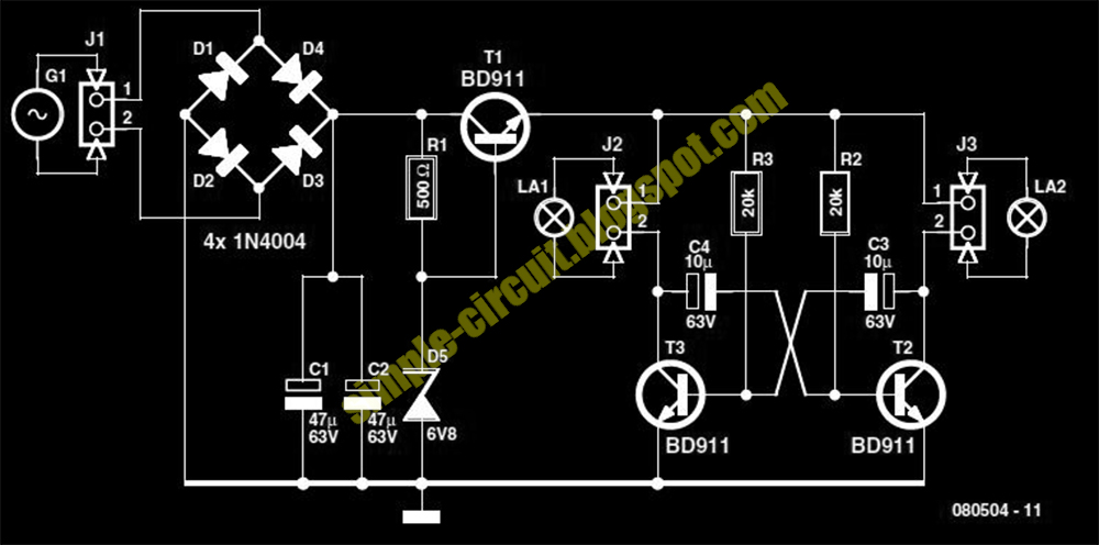
front wheel, one which has a dynamo already built in the hub. This supplied a nice sine wave of 30 Vpp (at no load). With this knowledge I designed a simple power supply. The transistors that are used are type BD911. These are a bit of an overkill, but there were plenty of these at my school, so that is why I used them. Something a little smaller will also work. The power supply is connected to an astable multi-vibrator. This alternately drives the front light and the rear light. This is the figure of the circuit.


You can use a 22 kΩ (common value) for R2 and R3, that doesn’t make much difference. On a small piece of prototyping board are six LEDs with a voltage dropping resistor in series with each pair of LEDs. Such a PCB is used for both the front and the rear of the bike. Of course, you use white LEDs fo the front and red ones for the rear. The PCB with the main circuit is mounted under the seat, where it is safe and has been working for more than a year now. There are a few things I would change for the next revision. An on/off switch would be nice. And if the whole circuit was built with SMD parts it could be mounted near the front light. This would also be more convenient when routing the wiring. Now the cable from the dynamo goes all the way to the seat and from there to the front and rear lights.


No comments:

Post a Comment

Powered By Blogger