Custom Search
WELCOME SIMPLE CIRCUIT DESIGN

Sponsor Links

Visitor Map


counter

Saturday, May 15, 2010

Simple Air Flow Detector Circuit


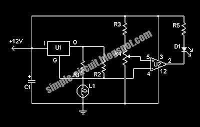
This simple circuit uses an incandescent lamp to detect airflow. With the filament exposed to air, a constant current source is used to slightly heat the filament. This circuit is using LM332 as main components. This is the figure of the circuit;


A comparator is used to detect this difference and light an LED. With a few changes, the circuit can be connected to a meter or ADC to provide an estimation on the amount of air flow.

Part:
R1 1 100 Ohm 1/4W Resistor
R2 1 470 Ohm 1/4W Resistor
R3 1 10k 1/4W Resistor
R4 1 100K 1/4W Resistor
R5 1 1K 1/4W Resistor
C1 1 47uF Electrolytic Capacitor
U1 1 78L05 Voltage Regulator
U2 1 LM339 Op Amp
L1 1 #47 Incandescent lamp with glass removed (See "Notes")
D1 1 LED

Friday, May 14, 2010

Simple Overture 30 Watt Audio Power Amplifier with Mute and Standby Modes


This is a circuit for a audio power amplifier that is based on single op amp LM4700. This circuit is a basic design. This is the figure of the circuit;


The LM4700 is an audio power amplifier capable of delivering typically 30W of continuous average output power into an 8 load with less than 0.1% THD+N. The LM4700 has an independent smooth transition fade-in/out mute and a power conserving standby mode which can be controlled by external logic. The performance of the LM4700, utilizing its Self Peak Instantaneous Temperature (°Ke) (SPiKe™) protection circuitry, places it in a class above discrete and hybrid amplifiers by providing an inherently, dynamically protected Safe Operating Area (SOA). SPiKe protection means that these parts are completely safeguarded at the output against overvoltage, under voltage, overloads, including thermal runaway and instantaneous temperature peaks.

[Circuit source: National Semiconductor Notes]

Simple Generator 9 V DC Unregulated Circuit


This is a design circuit to generate the -9V supply that is used by the row drivers as the off voltage for the TFT gate. This circuit is very simple design using LM2622. The LM2622 can be used in conjunction with a diode inverter circuit. This is the figure of the circuit;


The diode inverter works in the following manner. When the switch of the LM2622 is open, D4 conducts and the voltage across C7 charges to approximately +9.0V. When the switch closes, the voltage on the SW pin is suddenly dropped to GND. Because the voltage across C7 cannot change instantaneously, the voltage between D4 and D5 is −9.0V when referenced to GND. In general, this configuration will generate an unregulated voltage that is equal in magnitude but opposite in sign to the regulated supply.

[Circuit source: National Semiconductor Notes]

Simple 18 V for Row Driver "on" Voltage Circuit


This is a design circuit for power supply 18 V. This circuit is used by the row drivers to turn on the gate of the flat panel display’s thin film transistor (TFT). This circuit is based on LM2622 as main controller in this circuit. This is the figure of the circuit;


The charge pump works in 2 stages. First, when the switch on the LM2622 is closed, C4 charges to approximately +9.0V. When the switch is open, D2 conducts and the voltage across C5 is +9.0V. Because C5 is referenced to +9.0V node, the voltage is +18V (developed across C6) when referenced to ground. The +18V supply is unregulated, but sufficient to provide the "on" voltage for the row drivers. It is also possible to add an additional capacitor charge pump stage to bring the total generated voltage to +27V. In general, this configuration can provide either a 2x or 3x multiple of the column driver analog output voltage as the row driver "on" voltage.

[Circuit source: National Semiconductor Notes]

Simple 9 V for Column Driver Analog Supply Circuit


This is a simple design circuit for 9V driver analog power supply circuit. This circuit is using LM2622 as main components. This is the figure of the circuit;


In this configuration, the LM2622 is set to operate at 600kHz (it can also operate at 1.3MHz if the FSLCT pin is tied high). The circuit comprising of L1, D1, C3, and the SW pin of the IC operate. The analog output voltage is controlled by the resistor-divider of R1 and R2. The voltage on the FB pin is internally fixed at +1.26V, so in order to have a +9.0V output, resistor values of 51kΩ for R1 and 8.3kΩ for R2 can be used. Voltages other than +9.0V can be generated by changing the ratio of R1 and R2.

[Circuit source: National Semiconductor Notes]

Dynamic Noise Reduction System DNR Circuit


This is a design circuit for noise reduction system. This circuit is based on LM1894. This is a simple circuit. This is the figure of the circuit;


The LM1894 is a stereo noise reduction circuit for use with audio playback systems. The DNR system is non-complementary, meaning it does not require encoded source material. The system is compatible with virtually all prerecorded tapes and FM broadcasts. Psychoacoustic masking, and an adaptive bandwidth scheme allow the DNR to achieve 10 dB of noise reduction. DNR can save circuit board space and cost because of the few additional components required.

[Circuit source: National Semiconductor Notes]

Friday, May 7, 2010

Simple Step-up PWM DC-DC Converter Circuit


This is a simple design circuit for PWM converter circuit that is based on LM2700 single chip IC. This is the figure of the circuit.


The LM2700 is a step-up DC/DC converter with a 3.6A, 80m internal switch and pin selectable operating frequency. With the ability to produce 500mA at 8V from a single Lithium Ion battery, the LM2700 is an ideal part for biasing LCD displays. The LM2700 can be operated at switching frequencies of 600 kHz and 1.25 MHz allowing for easy filtering and low noise. An external compensation pin gives the user flexibility in setting frequency compensation, which makes possible the use of small, low ESR ceramic capacitors at the output. The LM2700 features continuous switching at light loads and operates with a switching quiescent current of 2.0mA at 600kHz and 3.0mA at 1.25MHz. The LM2700 is available in a low profile 14-lead TSSOP package or a 14-lead LLP package.

Powered By Blogger